485 I/O Expansion Module -4/8/18 channels
Product model:
Classification:
Attachment Download:
Product Description
1.Product Dimensions and Appearance
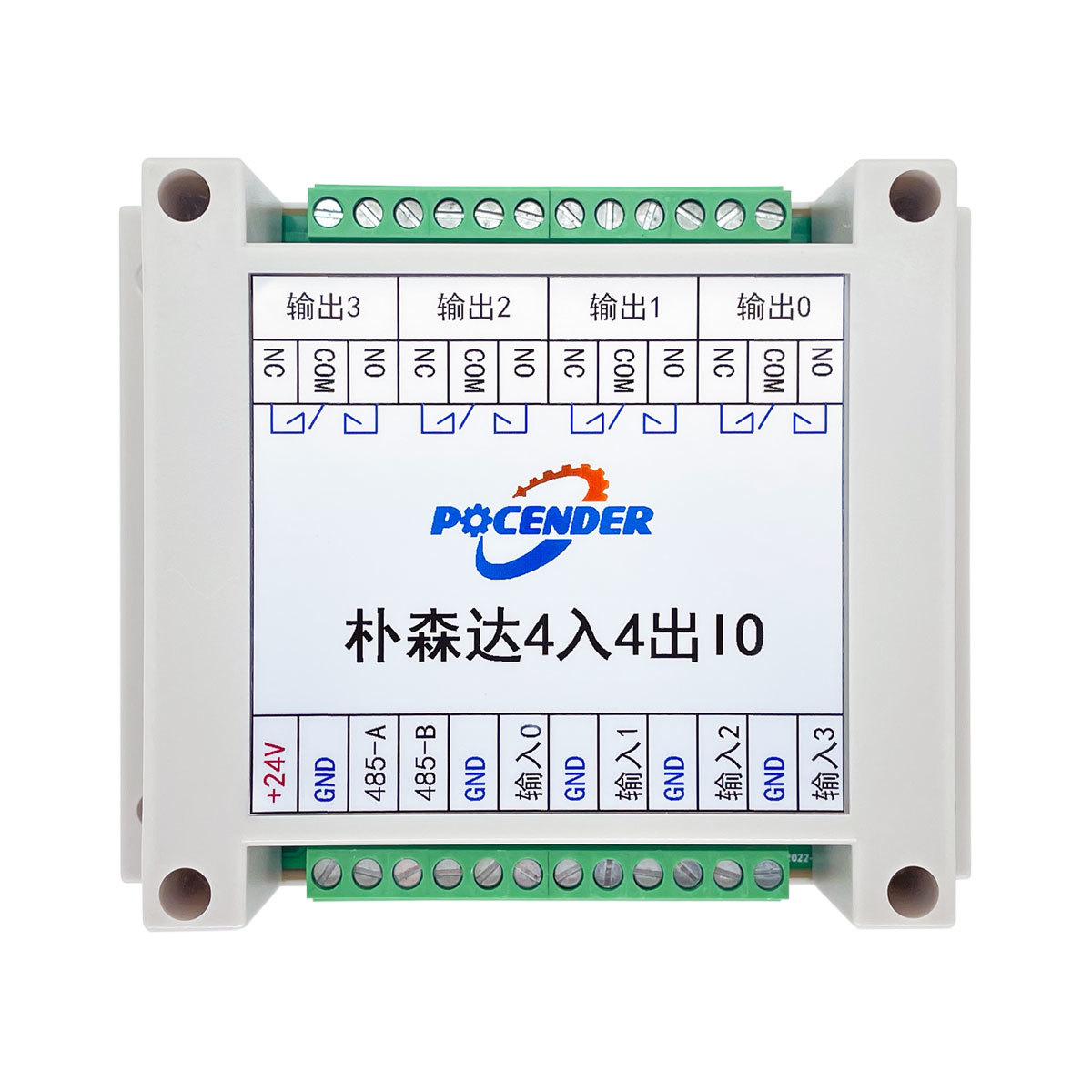
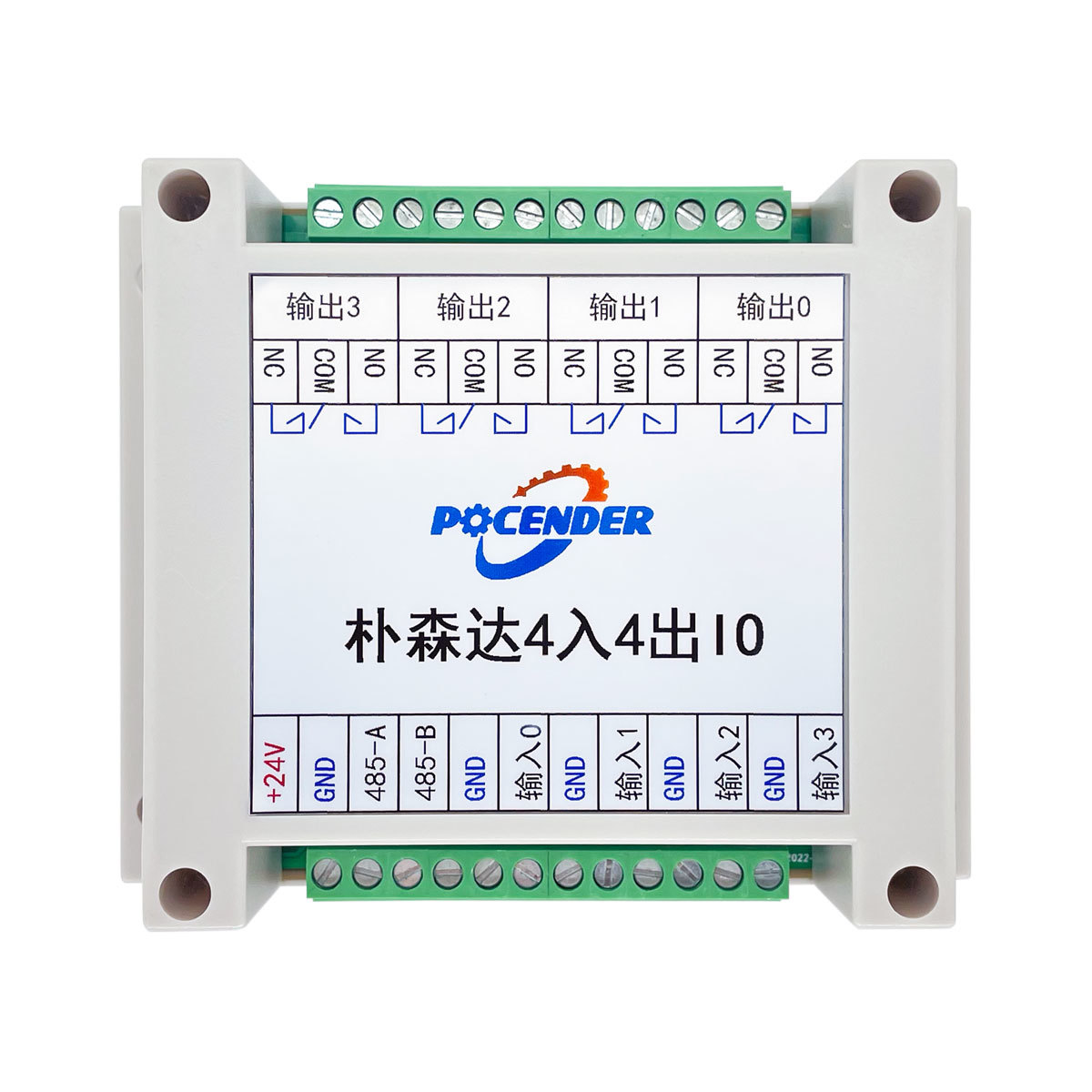
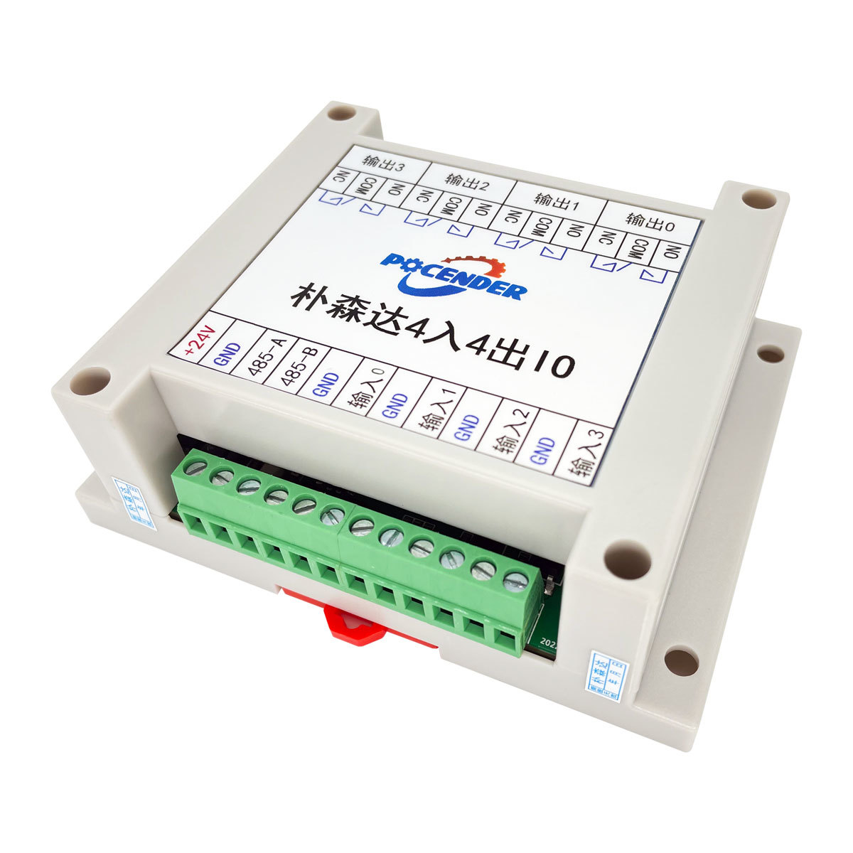
1)4-Channel I/O Expansion Module: 115x90x40mm
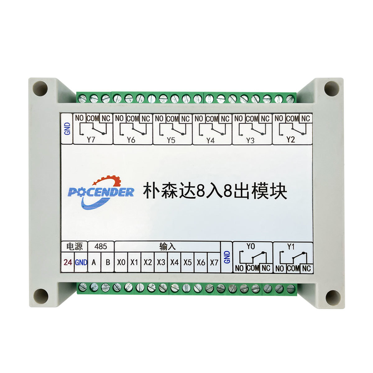
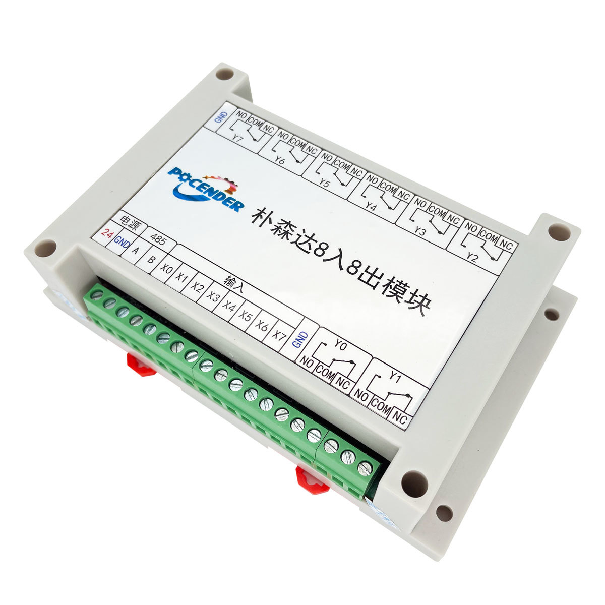
2)8-Channel I/O Expansion Module: 155x100x50mm
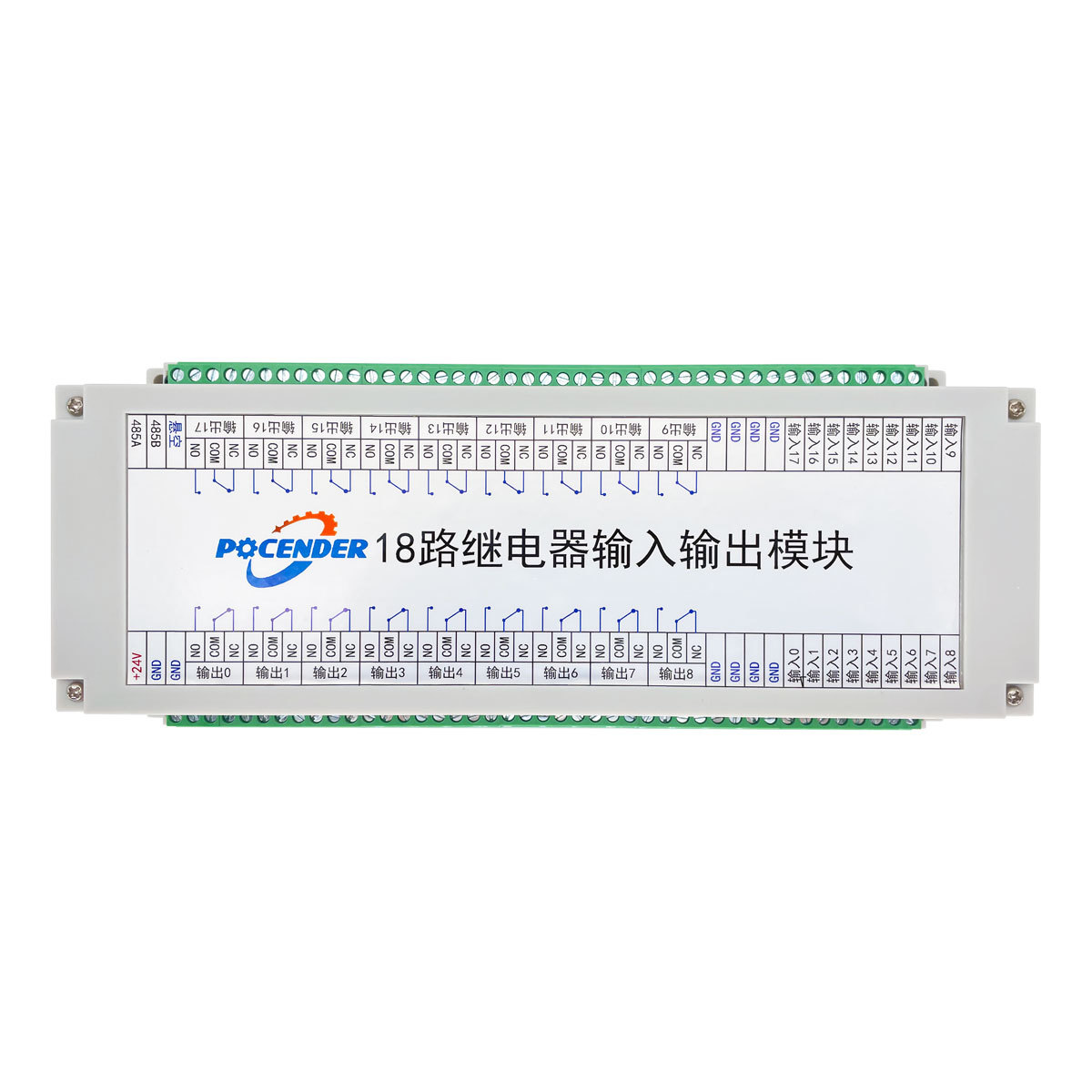
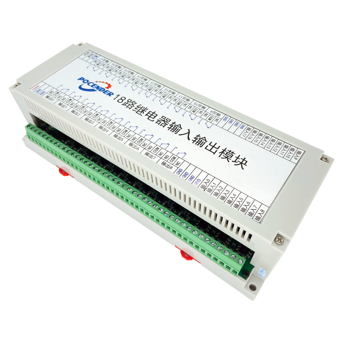
3)18-Channel I/O Expansion Module: 250x110x65mm
2.Specifications
Supply Voltage: 12V DC / 24V DC
Lifespan: >100,000 cycles
Input Type: Opto-isolation
Input Voltage: 10~30V DC
Communication Interface: Isolated RS485
Communication Protocols: Standard/Extended Frames
Communication Distance: 0~1200 meters (can be extended using repeaters)
Baud Rates: 29600/14400/19200/38400/56000/57600/115200 BPS
Communication Address: Configurable from 1 to 255, with power-off memory retention
Parameter Reset: Reset button, software reset
Mounting Method: Standard 35mm DIN rail
Indicator Lights: Power/Communication/Input/Output
Protection Functions: Overcurrent/Overvoltage/Reverse Connection
Operating Temperature: -40°C to +85°C
Operating Humidity: 0% to 85% (non-condensing)
3.Functional Description:
1)Outputs (Up to 18 Channels):
Controlled by M Codes
M62P0-M62P15: Activate Outputs 0-15 (16 Channels in Total)
M63P0-M63P15: Deactivate Outputs 0-15 (16 Channels in Total)
2)Inputs (Up to 18 Channels):
Custom G-Code Functions (e.g., G0X0Y0)
Custom Functions for Start/Stop/Resume/Homing, and more
M Code Input Functions and Waiting for Input Features
Signal Inputs:
X0: Default for tool clamping cylinder safety detection.
X1: Default for tool disk ejection cylinder signal input detection.
X2-X9: Custom Button Inputs
Signal Outputs:
● Relay 0 is assigned to the tool engagement signal. Caution should be exercised.
● Relay 1 is assigned to the servo-driven tool magazine rack extension signal. Caution should be exercised.
● Relay 2 is assigned to the automatic switching signal between position mode and velocity mode for the servo spindle. Caution should be exercised.
● Relay 3 is assigned to the output signal for the chip door cylinder in the tool magazine. Caution should be exercised.
● Relay 9 is assigned to the air blow output signal for the tool setter. Caution should be exercised.
● Relay 10 is assigned to the alarm display signal for the tricolor lamp (red).
● Relay 11 is assigned to the pause/idle/manual output signal for the tricolor lamp (yellow).
● Relay 12 is assigned to the running signal output for the tricolor lamp (green).
Key words:
Standalone CNC Control System | CNC Control Programming OEM | CNC System Retrofit
Recommended Products
Product Consulting


